Showing posts with label electronics. Show all posts

eBike - Electric bike lights

Mrs 120ThingsIn20Years pulled up in her eBike only to grab a hand rail and detach a bit of tendon that should have never been detached.

Ouchie!

She's under the Plastic & Re-constructive Surgeon's knives, scanners, and other bits of kit as I type. So this is part blog post, part self distraction.

We are so lucky in the west to have access to all these amazing experts who learnt all this amazing stuff from all our amazing universities, then went on to work at places with amazing tech that can do amazing things.

Head transplants and so forth.

Sometimes medical staff (oneofmyformerelderlyGPs) forget they didn't get there on there own, but rather because we wanted them to be put there so found the cash to teach them, and that perhaps the poor people in the hospital where they used to work were poor because they were sick or something, and not just because they loved daytime television.

But more often than not they are an awesome bunch of people.

So thanks medical type people everywhere. If it wasn't for you, I would have been dead ages ago, many times over.

Now...

Tail lights and indicators had nothing to do with this mishap, but I cant help feeling it might be nice to not have to take your hand off the front brake (right hand) to signal a right turn across traffic (we drive on the left). If you don't signal you run the risk of getting killed, and if you do, you will almost certainly be killed.

Especially by that loony driver who was driving on a moonless night with their lights off. Thanks loony driver for near missing me. A near miss is always better than a light graze.

Anyway, I thought I'd make some indicators and brake lights and things.

I figured I'd use a PICAXE programmable chip to make everything work.

I further figured the feature list should be ...


  • Headlight control so I can set strobe, always on, hi/low beam or whatever. This way I can add my own light directly to the eBike power supply at some stage, and turn the world into daylight if needs be. When we are on the road, a strobe headlight is always a good thing so you don't get lost amongst all the other white lights. But we have a lot of cycle tracks in Adelaide Australia, and when you're on the tracks, being able to see is more important, so you want solid bright light.
  • Turn indicators with a handlebar mounted three way thumb switch with off in the centre, and some kind of beeping sound that reminds you that they are on. Maybe a auto cancel function after 30 seconds (with an extra beep to let you know or something).
  • A brake light that does something dramatic to draw attention to itself, and when it's not being used as a brake light, should just go about acting like a normal tail light.
I think it's important to have a solid red light (most bike tail lights here strobe) to give the indicators a point of reference. It's will be difficult for a driver to tell if your indicator is the left or right without a red light reference point I think. 

For the brake light drama, I'm thinking along the lines of a rapidly increasing strobe that flashes faster and faster, then settles on solid bright red light. The flashing stage would take perhaps one second and should continue even after you take your hand off the brake, so you can use it as a "HERE I AM, LOOK AT ME" kind of thing. Just touch the brake when you think people need to be reminded of your being made of soft squishy stuff that goes all rancid when all your blood falls out, and then you can get back to escaping from them.

Then one last feature should be a "strobe everything" function in case of emergency. I might also attach that to the warning device.

My current warning device is a bell, but it's soon to be upgraded to a container ship's fog horn, and a baseball bat with a nail through the end of it.

Actually I think I might start a campaign that says a green flashing light on the end of a flexible fibre glass rod that extends two feet into traffic means that there is a diamond on the tip of the rod ready to gently (without disturbing me in the least) draw a line down the length of your car's paint if you get too close.


120 Things in 20 years thinks that the emergency "strobe everything" function would be best voice activated by a scream.


Photography - My new macro-bot

I built a thing today.

It moves stuff in small increments using a small electric motor, in response to a users input.

I guess that means I've built my first robot.

Actually, probably my second.

Anyway...

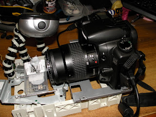
My device looks like this


It also looks like this.

The bit with the "1" next to it is my previously built power supply that delivers 5 volts to my project.

The bit with a "2" next to it is the previously made PICAXE Proto Board that connects some input/output pins to my breadboard.

The "3" is the transistor bit, that powers the motor when the chip sends a signal to do so.

And the "4" isn't really visible. If you could see the "4", it would be next to the the switch that the user presses to make the subject move a tiny bit.

The point of this exercise is to attempt to make a device that carries an empty box of mints along a steady track, to carry a subject to different focal distances, in order to make a series of photos to create a focus stack, and thus create an image with a greater depth of field than might otherwise be achieved.

This absurdly simple solution, represents my first successful attempt at creating an electronic something without external help from someone, somewhere on the planet.

All the software does is wait for someone to press the button, then move the subject a tiny bit closer to the camera. This changes which bit of the subject is in focus, and enables the user to take a "stack" of pics, each one having a different plane in sharp focus. The user can then knit them all together using some free software, creating a photo with an otherwise impossible depth of depth of field.

The 11 lines of code that makes it work look like this (the very small amount of black text is the actual software, the green text is just my description of it)

--------------------------------------------------


; Macro Mover ver 2013 06 10 0200
        ;moves a small platform holding a photographic macro subject a tiny amount closer to the camera         '            each time a button is pressed, helping to create a "focus stack"
;120thingsIn20Years.blogspot.com
;no rights reserved
;use at your own risk

;For picaxe 08M2

#No_Data 'saves a few seconds when uploading the code to the chip, because it doesn't have to check for data

main:' begin the main program loop

if pinC.1 = 1 then gosub Move    'if someone is pressing the button, jump to the bit of code called "Move"

goto main ' if it gets this far, go back to the start and check for a button press again

Move: 'the bit of code that moves the platform with the subject on it

do until pinc.1 = 0 :loop ' hang here until the button is released

high 2 'turn on the motorconnected to pin 2
pause 2 ' wait for 2 milliseconds
low 2 ' turn off the motor connected to pin 2
pause 100 ' pause for 100 milliseconds

      return 'go back to the gosub that called the "Move" code

-------------------------------------------------


I started with an old CD ROM drive that I ripped all the interesting bits out of.

I think this is the original motor because it fits perfectly. This is the motor that made the laser head move from the centre to the rim. Now it's the motor that moves the photographic subject towards the lens, changing which bit is in focus.

The blu-tac is there as a weight to keep the linear cog in contact with the gear that the motor connects to.


So the motor makes the black bit move from this extreme...

(see the black bit)


to this extreme, but in tiny increments each time the button is pressed.

Each button press causes a a quarter of a millimetre migration.

.25 mm = 0.0098 inches

A tiny amount each button press.

The camera sits on the large grey platform to the right.


The software controls how much the motor moves at any given moment. This way we control how much we increment the slice of our subject that is in crisp focus.

The camera is securely set in place because there is a tight fit due to my bending some tags in order to hug the camera. There is also two lumps of blu-tac securing the camera to the base.

This arrangement feels totally secure, and I haven't had any problems with the camera moving.


Last, but far from least, I added a subject platform  and a light source. The subject sits on a platform made form an empty tic-tac (small mint confectionery) box,

The light source is the thing on three zebra legs.

It's best to move the light source with the subject as it moves toward, or away from the camera, to avoid photos with different exposures, so a light that moves with the subject is best.


Once you have a "stack" of photos with different bits in focus, you can knit them all together with a program like "MacroFusion" (free, open source program I run on my linux computer)

To use this Macro-bot device, you press down once or more times, on a button to move the subject a tiny bit closer to the camera. After each button press (or two or three) you take a photo. Each time you press the button, the subject moves a fraction of a millimetre. I found pressing the button once was suitable for macro shots where the lens was at full zoom, and pressing three times when the lens was at minimum zoom.

Some experimentation is required, but as soon as I made this, I immediately solved all the problems I was having with poor alignment of my photos in a focus stack.

Successful results to follow...


120 Things in 20 years - Sometimes, all you have to do to make a robot, is to replace all the bits from the robot you salvaged last week.


Electronics - Inverter repair

An inverter is a useful thing. It takes a stack of electrons from a 12 volt battery, and makes them look like the stuff that comes out of your wall, in my case at 240 volts.

How it does it is anyone's guess.

In my case it doesn't actually do that. In fact all it does, is take a stack of electrons from a 12 volt battery, and turn them into the smell of melting value.

I couldn't understand why a perfectly interesting looking device should fail.

Here it is pictured after it was repaired, but it also looked pretty much like that when it didn't work, but now I've given away the ending to this tale.

I fixed something - a first.

Note the total absence of left over bits - also a first.


Normally, the plan of attack is to open the device up, then put all the left over bits in the bin next to the now slightly more hollow, and slightly lighter device.

But this time was different.

To begin with I already knew why it was making all that melting plastic smell.

It was over heating.

The thing has a fan that is presumably meant to spin around a lot. At least I hope it's meant to spin around a lot. If it isn't meant to, it does now.

Perhaps I just invented something....

To make an artificial breeze, simply take a normal fan, and make it spin.

So...

The point is the fan wasn't spinning. I have a few fans that I've pulled out of junked computers, so I figured I'd just replace it. I can solder a bit now as well, so I figured it should be easy.

There were even some obvious screws to undo.

I used the electric screwdriver my mum bought me as part of a present.

Thanks mums everywhere. It even has a torch built in and you can never own enough torches, even when you will never use them.

I always thought electric screwdrivers were a bit pointless, but it turns out they are excellent. I've just never actually needed one before.


Unlike this project, my last had a few bits left over, and this was where the electric driver was really useful. It turns out there are a zillion screws inside stuff.

Pictured is all the leftover bits not including all the gears and shafts and all kinds of springs and stuff that might come in handy one day.

"What are the chances of any of it coming in handy?", I hear you ask.


But that's what they said about the 200 short lengths of black poly irrigation pipe I still have in the shed.

This thing used to be one of those fax, copier, printer combo devices that wasn't working any more. A friend was throwing it away, and thought my car was as good a place as any to throw it. It turns out there are some good motors and gears inside. I think there were five motors in there. That's them on the right. Maybe six motors. I'm planning on needing some motors, gears, and some shafts for making my solar tracking heliostat. There are also a stack of salvaged components used for tracking the placement of motors. The motor on the bottom right has a spoked arrangement that passes between a censor that detects light, and a light. The shadows cast by the spokes allow the system to track where the print head is. Or so I've read.

So much to learn. So much time. If you just stop watching TV.

Anyway, I've drifted off what pretends to be this post's topic...

Ok, so the fan wasn't spinning.

None of the fans I had would fit exactly, and would have to be trimmed (hacked and snapped with a pair of pliers) until they could be coaxed into duty.

I looked under that foil label and found the exposed end of the shaft.

I thought I'd drop in some oil before I replaced the fan to see if that's all it needed. It was.


The black, and off white cylinder in the front with the brown stain at the base is a capacitor.

I'm guessing it was also the source of the burnt plastic smell.

So that had to go. Luckily I have stacks of different capacitors from pulling apart some stuff, and had a duplicate.

A big component with large nicely spaced pins that proved easy to solder.

The thing went back together with no left over bits, and no spilt coffee added.

I realise this was a very simple repair, but it is something I would have sent to landfill before learning a bit of electronics over these last few months.

Here is a terrible photo of it charging a phone through it's transformer, and maybe a bit of Bigfoot's leg. Who can tell.


A 12v car battery supplying an inverter outputting 240v, then through the iPhone transformer to bring it back down to 5v.

Ok it's slightly inefficient, but the phone was the smallest thing I could take to the car to test it.

I rate this a total success.

Which is nice.


120 Things in 20 years - Bringing me one step closer each day to being able to take down a Terminator. Or repair an inverter. I need to win a 3D printer.

Electronics - New fish lever switch

I was wandering around wondering in an electronics store today, and found a new, even better switch  for my fish activated lever on my demand fish feeder.

It looks like this.

The one on the left is what I'm using now, and I had to glue some tubing on it so that it looked more like the one on the right.

The one on the right already looks absurd without my having to glue anything to it at all.

I have no idea why someone would need an inch long press button switch.

Unless they were using it as a fish lever.


I mentioned to the owner that the switches could be triggered with sideways pressure.

He didn't know that.

It seems the manufacturer didn't intend it, and it is just a pleasantly useful side affect of the manufacturing process. .


120 Things in 20 years - Getting ever close to filling up my brain with new facts about electronics and absurdly long new fish lever switches for my aquaponics demand feeder.

Electronics - Breadboard multimeter adapter

For some time now I've been looking for a convenient way to probe around my breadboard with my multimeter. It can be a little tricky, because the probes are too thick to get into the little holes on the breadboard.


I had a bit of an idea today.

I came up with this...


It's a stereo headphone jack with a long length of header pin (sturdy wire used as a plug) soldered to the legs.

I added some insulation in the form of heatshrink, and...

TaDah!

The 120 Things in 20 years multimeter breadboard adapter.


Electronics - Aquaponics - Demand feeder fish lever build

I spent some time in an electronics store testing long buttoned momentary switches.

They all seem to work when you tilt the button to the side as well as when you press the button normally. Perhaps they are designed to work that way after all.

Thanks button maker.


I had a bit of a breakthrough with the entire lever, and not just the switch part. I found this fishing float had a white plastic bit that almost fit over the momentary switch's button.

That's the switch lower right.

The white plastic thing was hollow, but needed a slight enlargement with a hand held drill.


The button went in with a snug fit, and the white thing was really their just to give me some surface area glue onto.


The new lever incorporated a second fishing float as the stem, and as a nice bulb for the fish to hit.

The float stem has a bit of flex to it, so it should be forgiving if a fish hits it hard.

It looked lie this when built.


I glued it in place with super glue, and held it while it dried with what to me looks like a naked chicken with a fist for a head.


So now my device looks like this.

It also works.

I turned it on, and while I was putting a cover over the fish tank, the bigger of my two fish hit the lever and got a feed.

I did have the camera running, but the video was too dark to post, but the switch and lever worked perfectly.

I count this as a success!


120 Things in 20 years suggests you never try to take your electronic aquaponics demand feeder on a plane with you, unless you feel like explaining it for a few hours.

Electronics - Aquaponics - Demand feeder lever

Probably the most difficult single thing to deal with in making my demand feeder has been working out the lever.

But as usual I called upon chance to solve it for me.

Thanks chance.

For some reason I remembered playing with a switch I bought when I was making the first version of this demand feeder. The switch was one that is a button, and turns on then off again after you lift your finger.

It's sideways click seemed nice to the touch.

The one pictured (centre front) is the same, but is on an old circuit board. I cant find my original version.


It's quite long for a momentary switch.


The interesting thing about these particular, particularly long momentary switches, is they they do their switching thing if you tilt the button to the side rather than just press it. I just tested this one and it works.

They also work if you press it, but it's the sideways switchyness that interests me. It should be perfect as the lever the fish hit, because they can hit it from any direction and it should trigger.


Now all I need to do is figure out which brand they are, and if they all work like that. It might be the case that only some of them do this. It might be a manufacturing error rather than a feature.

Perhaps manufacturing error is too harsh.

Perhaps manufacturing  tolerance would be better.

Either way, I might be able to use it.


120 Things in 20 years - As luck might have it, for the next few days, you might find me in electronics stores with a multimeter, trying to find a switch for my electronic, aquaponics demand feeder lever.


Heliostat - What's a heliostat?


I want to start building a heliostat, with the eventual goal of making a solar tracker, but for now, I really want to just build something that will send light through my window.

Why? You may well ask.

And "What's a heliostat?" you may add.

A heliostat is the kind of thing someone with a water drop lensed microscope might have used to get some light on the subject*. Early models involved humans, who were forced to point shiny things in such a way as to reflect the light to shiny men's laboratories. Later versions incorporate wind up mechanisms. For a single day device, all that's required is that it turns 15 degrees every hour, as long as you are willing to manually adjust the elevation for the particular day you are using the device,
a heliostat will track the sun so that a mirror will always reflect to the place I want the light.

The solar tracker is like a heliostat, except that the place it's pointing at is always moving. (that point being directly at the sun wherever it is. But the solar tracker is for another day. Actually all of this is for a great many days.

For now, I'll be working on a small digital device that controls the direction a small mirror is pointing, to make it always reflect light to a fixed point. Basically a way to bring some natural light through a window that doesn't see a lot of light.

There seems to be a few different ways to create some linear movement. Linear movement being required to lift a side of the mirror to adjust the direction of the reflection in the up and down aspect.. I figure if I can raise or lower one side, and make the entire device pivot around a mast, I should have all the degrees of movement required.

According to the invention engine, one way to create the required angle might be to glue a hinge to a mirror, and mount that to a mast to support it. Tie a string to one side of the mirror, then wrap it around a tiny winch mounted half way up the mast, then tie the other end to the other side of the mirror. That would give me up and down, and then all I need is a way to rotate the entire device, perhaps using a geared motor, and a pulley.

I haven't really tackled this bit of the design, but the control of the motors could be done via a PICAXE chip similar to that used in my demand feeder. and some light dependant resistors (LDRs).

If two LDRs were arranged so that when the device was pointing correctly, they were both in full light, but when one became shaded, the motor could be turned in the correct direction to make the adjustment.

A similar arrangement could be made for both the up and down, and rotational movements.

I'm off to an electronics store to buy some stuff.


*may not reflect reality.


120 Things in 20 years is busy finding bits of heliostat. 


Electronics - Aquaponics - Demand feeder hits

It turns out the fish have been hitting the lever, but the switch hasn't been working.

It should be an easy fix, but for the time being, this will have to do.

[edit from the future - I fixed the switch and got a few proper hits with feed delivered within a few hours]

Electronics - Infinite battery life camera

I've had to make a few compromises with version 2.0 of the demand feeder.

One is that I've re-written the code and made it a lot more simple than it was originally. I've still got the old code, and I'll use it and post it when I make it a little better, but the full version resets each day at dawn as one of the overfeeding protection measures. I only have two silver perch in a 100L fish tank, with 300L of filtration media, so they can have as much feed as they like. To encourage the pressing of the button, I've made it so that they only get a small amount of feed each time, but they have the opportunity of more feed after only eight minutes since the last feed. The point of making a simpler version of the software was so that it would keep a running total of all events like the number of times the fish have hit the feed lever when the light is lit, and the number of times when the light isn't lit.

The fish pressed the lever only once in the 24 hours since I added it to the system. This may have just been a tail swipe, but it would have delivered feed, so some reinforcement of the behaviour of getting at least near the lever has begun!

It wont take them long to get the hang of it.

I ran the camera until the batteries were dead last night, but the hit must have happened some time since dawn while the camera was on charge. To solve this two hour filming limit, I created this.

It's a camera taped to it's battery charger, that is in turn taped to a tripod.

I plugged it into the earth leakage safety switch that the rest of the system is plugged into.


It blends in a bit with the actual feeder, but that's the feeder with the birds nest of wires sticking out of the back of it. The orange looking light under the camera is the LED that tells the fish feed is currently available. The red light at the top is the power on LED, and the yellow one is flashing out the number of feeds allowed in a day (even though the thing no longer resets after a day, so really it shows the number of feeds allowed ever). There are also LED's that flash out the number of feeds so far, the feeds remaining, the number of attempts made at the lever when food isn't available. That is when the feed LED isnt lit, because they just fed recently. And one more that flashes out the size of each feed that's delivered. The size is measured by how long the motor is on for, and doesnt actually represent the amount of feed, but on average, should spill a predictable amount each time. Currently, they would get around 5-8, 3mm pellets each time they hit the lever.

Hopefully, I'll have some video soon.


120 Things in 20 years - Electronics - Infinite battery life camera - This project is far from finished.

Electronics - Zero K breadboard resistor

I always try to not just "take" when it comes to learning a new thing, but this electronics caper has really been worked out already by a whole stack of really clever people.

I cant seem to come up with anything to offer the world, so I came up with this as a forlorn attempt to quench my karmic debt.

It's the zero K breadboard resistor.

It's a wire with a knot in it.

It works just like a wire, but is easier to handle.

It's all I've got at this stage.


My karmic overdraft doesn't seem to have changed.


120 Things in 20 years says, "When thinking electronics, a zero K breadboard resistor can be simultaneously just right, and not quite enough.".

Electronics - Motor repair success

I fixed my broken motor that is meant to power the auger via the tiny gearbox that will deliver the fish food in my demand fish feeder.

Normally I prefer less complicated sentences.

But I'm all excited.

It turns out, the problem was there were simply too many parts.

Or more accurately one too many parts, and one that was simply in the way.

The silver bit was the one too many. I think that broke off the bit where the wires connect, and fell into the motor, generally clagging things up.


The little nylon washer creates part of the front bearing, but it made getting the brushes back on impossible, because it had to be put on after the brushes. That's an impossible path through the plastic front. I don't have the kinds of quantum tools that walking through walls requires. And if I did, I wouldn't waste my time with motor repairs. I'd do much more interesting stuff, like poking my head through the fridge to see if the light really does go off when the door is closed.

So be leaving out those two small parts, I managed to make my motor work.

Only two parts.

And they were tiny.

Those that know me will realise that's a pretty low number of excess bits after a repair. I think I did quite well.

So well in fact, that it looks like this when it's running.

That should do nicely.

What this all means, is that there is really no reason why I cant put this thing together today, and actually finish something.

Maybe.


120 Things in 20 years - If I keep repairing them, one day an electronic motor repair might leave me with enough parts to eventually build another motor. I should fix cars.

Electronics - Aquaponics - Demand fish feeder software


As far as I know, the software is all working on my demand fish feeder.

It's a bit of a mess, with a few goto statements and a few unused variables. I'll fix it in time, but for now I'm going to move onto getting a finished product up and running. As far as I can tell with the software simulator everything works, but the real world might be a completely different story. (the breadboard version also works)


A switch lever extends down into the water. If a light near the lever is lit, the fish can press the lever and feed is delivered. Feed can also be offered with an override button that sets the light on and the feed on if the fish hit the lever (so you can show people how it works)

Dawn detection seems to work. In the end I went with two startup options.

1. A human who holds down the FeedNow override button during startup, then taps out the approximate number of hours since dawn. This skips the code that searches for a new dawn.

2. An abnormal restart with no human. This stops all feeding (there might have been a blackout, and subsequent ammonia buildup) (note to self - add code that flashes some lights to indicate the device is in abnormal start mode so a human can reboot it if they desire). Feeding resumes after night time is detected, and a dawn is detected.

The user can select (via a screwdriver to resist little finger making their own adjustments) ...

 - the feed amount per day in tenths of a second of motor on - from 0 to 65 (I'm guessing I'll use 1/2 a second per feed event) The motor turns an auger under a hopper full of feed. So there is another adjustment available

- The number of feeds in a day that are offered (0 - 255 per day)

- The level of light at which dawn is detected. This allows for a system built in the glow of a streetlight or whatever. At dawn each day, all the numbers reset. This is a bit of a problem as far as reading how many feeds were delivered in a day, but for now I'll leave it as it is. My fish feed like crazy at dawn, so I want to give them the greatest opportunity to feed. Eventually I'll add a data logger, so it wont matter when it resets.


The system reports...

- the number of hours since dawn

- the number of feeds since dawn

- The number of false hits to the feed lever when the FeedIsAvailableLED is NOT lit (these will go down to near zero once the fish learn they can only get food when the light is on)


I ran out of feed a while back, and have been feeding my two big silvers on duckweed, lettuce, and worms, so I will need some pellet food before I can test it in the real world. (I still have the PVC device from the first version).

I'll also need a motor as my original one is no longer with us.

The feeding regimen isn't very intelligent at the moment, but I'll do a bit of research, and add some code that tries to deliver the maximum amount of feed in a day that the system can handle. This will probably involve allowing 3/4 of the feed to be dumped at will, with the rest being spaced out over the day ... or something. I haven't given it enough thought because I don't really know what the fish need. My experience in fishing for wild fish indicates that the feeding pattern is far from a constant grazing all day long. I'll work it out.

But...

It's going to work. In fact, it already does.


120 Things in 20 years That's all. Just 120 Things in 20 years.


Electronics - Reasonable success milestone

What's pink and white, and looks a bit like a short alien under stage lighting, talking to a tall man with a diode for an upper leg, and a friend with a paper bag over his head?

Nope.

Too much Christmas spirit.


120 Things in 20 years - Electronics - Demand feeder diorama 


120 Things in 20 years - As at 2012 12 24 23:56 my demand feeder actually works (if you include a light where a motor should be as "working" (which I do)). I declare this point in time , an Official reasonable electronics success milestone.

Electronics - Aquaponics - Motor woes

I found out what was wrong with my motor.

I'll start that again.

I've been having trouble with my motor.

I opened it up and found what the problem is.

Too many parts inside just rattling around doing nothing.

I'm trying to explain to them that everyone has to pull their weight, otherwise nothing gets done.

So far they are ignoring me.


It's hard to fix something when you have no idea what it looked like before it was broken. Firstly, the bit of metal on the end of the yellow wire has to fit through a hole that's half the size of the bit of metal. But it did just fall out through that hole.

Clearly someone's being funny.

There are two bent bits or copper that look like they make contact with the shaft, but I cant see how they could without wearing out, But then, they are actually worn, or at least they look worn. but if there are magnets on the outside that don't have power going to them, and a rotating shaft with copper coils that gets it's power through these copper bits, why not just build the thing inside out, with the coils on the outside, stationary bit, and the fixed magnets on the inside. That way you would avoid the need to put power through a rotating shaft.

I must be missing something 


120 Things in 20 years - Electronic and Aquaponic motor woes, and much of the world, are confusing.


Electronics - Aquaponics - Demand feeder version 2 schematic

I've been busy.

I've been busy learning how to create a plan, and a circuit schematic to go with the plan.

It looks like this, and I think it might be finished.

I now know a stack of stuff that I didn't before.

Things like...

It's ok to not connect up the earth (0 volt) wires in a schematic.

You just label them as earths, and leave them hanging in the wind.

It actually makes the diagram a look a lot better to read. (thanks SuperVeg)

When you make a real version, all those earths, are connected to the power supply's negative terminal.


So now that I have a plan and a circuit diagram, my next step will be to build a working model on a breadboard, then solder the real thing together.

I've already started.

I've also started to write some of the required software.


120 Things in 20 years - It's 3am

Thinking - Electronics - Education

I'd like to take this self created opportunity, to comment on my experience of the South Australian education system.

It was really, really boring.

For example, the following two phenomena would have got me very interested in science, but were conspicuously absent.

Did you know that if you stick a powerful magnet on a battery, then reach a copper wire so that it balances on a point at the top, and just slightly touches the magnet on the bottom, the device creates a stack of rotational motion?

I didn't, and I've been to school.

It looks like this...


And if you add that failure to educate me to this other example, you see why I'm a little disappointed...


In this second video, the rare earth magnet creates a magnetic field in the copper pipe, and that reacts with the magnet using ordinary magic.

 Both videos are real, but totally lacking in my childhood experience. 

Not happy.


120 Things in 20 years - When thinking about electronics, and education, I want my money back. 


Electronics - Aquaponics management system

I've decided to remake my demand feeder from scratch.

I just couldn't figure out what was wrong with existing model, and it may well be because there were just some random bits soldered on. Some stuff didn't seem to serve any function.

So I thought I'd start with some proper documentation and some kind of plan. That way I can work out which chip I need, depending on what functionality I require, and also some plan for expansion.

I also plan on making it work as a demand feeder before making it do anything else like regulate how much feed the fish can have. At the moment my fish can have as much as they want, because I have much more filtration system that I need to cope with only two fish.

The plan looks like this at the moment.

I just started.


I realise that isn't very informative as far as pictures go, but it does in some small way, indicate just how much more I have to do.


120 Things in 20 years - I'm exhausted already just thinking about thinking about the plan on how to make an electronics based aquaponics management system.


Aquaponics - Electronics - Digital demand fish feeder

The water temperature in my aquaponics fish tank is today sitting at around 20c This means my silver perch are back to feeding like crazy.

I suspect they would eat a lot more if I fed them 20 times a day, so I rummaged around in the darkest depths of my house, and found my demand fish feeder project.

When I made it as part of trying to learn electronics, I happened to be on lots and lots of morphine because I had a rock festering in my kidney. At least I think that's what it was for.

Geology is interesting and all, but who wants to grow rocks in your kidney.

Anyway, it seems that whatever you learn when your brain is in an opiate fog stays in that fog. At least it did for me.

Every now and again I've discovered this poor little open source project, and tried to figure out what it does, and why it doesn't do what it should do, and it always ends in my just putting it back into the darkest part of my house, and leaving it there until for some new reason I think I'll understand it again.

Yesterday I looked at it and it made sense.

Only a bit, but that's a bit more than usual, and I wasn't even on morphine.

I traced everything from the pins to whatever input or output  (switches or lights) devices were attached, and almost all of it seemed to do something. The three adjustable gizmos (pots) in the top right are not connected, but I looked at my code, and worked out what they should be connected to (they adjust food amount, total food allowed in a day, and light sensitivity to trigger the dawn reset.

There are also these four resistors that dont seem to do anything.

I'm guessing they are either, connected to the potentiometers (adjustable gizmos) or have something to do with the second circuit that I found.


The second circuit looks like this, and I'm pretty sure it was meant to be mounted like this.

It has a button and a switch.

I remember making a water proof override switch so I could give the fish a dose of food when I visited them and wanted to see them hit the demand lever and get fed.


Now the four resistors might be for the pots, but I cant remember if they needed resistors. They are, after all, resistors.

I think.

But some things need resistors so they don't feed ambient static into the chip, and give false readings that look like button presses or whatever.

Who knows, but it feels a bit like I'm almost, right on the edge of nearly being back on track.


120 things in 20 years Aquaponics - Digital demand fish feeders are sometimes better off recycled and started from scratch.


Electronics - Power supply

One of the biggest problems I have with designing electronics is that I don't know anything about it, and don't know what all those little components do, so I designed this....


There are lots of bits missing, but I didn't want to go any further without getting some input from someone who knows this stuff, so I thought I'd post it any way.

It's more of a question than an answer.

"Is this something?"

The switches in the dotted line boxes are controlled by a chip.

The plan is that the capacitors would be charged either in series or parallel, so chip compares the voltage of the caps or source, and compared to the desired output voltage, it could then mix whatever capacitors it needed to achieve  the desired output voltage. With the battery (right hand side of the circuit) disconnected, the capacitors would be charged. Then the source power (left hand side) would be disconnected, the number of capacitors needed would be calculated depending on desired voltage, then they would be opened to the battery. So it might charge all the capacitors in parallel, then discharge the required number into the battery in parallel (or whatever).  This might happen a thousand times a minute or something.

I'm trying to create an "anything in, anything out" power supply that doesn't waste any power. That way I can charge my battery on my boat form a solar panel, plus a bit of wind power, and whatever else I happen to plug in.

I doubt it will work.


120 Things in 20 years dropped out of Eh?lectricity school. Can you tell?


Popular Posts