Showing posts with label PICAXE. Show all posts

eBike - Electric bike lights

Mrs 120ThingsIn20Years pulled up in her eBike only to grab a hand rail and detach a bit of tendon that should have never been detached.

Ouchie!

She's under the Plastic & Re-constructive Surgeon's knives, scanners, and other bits of kit as I type. So this is part blog post, part self distraction.

We are so lucky in the west to have access to all these amazing experts who learnt all this amazing stuff from all our amazing universities, then went on to work at places with amazing tech that can do amazing things.

Head transplants and so forth.

Sometimes medical staff (oneofmyformerelderlyGPs) forget they didn't get there on there own, but rather because we wanted them to be put there so found the cash to teach them, and that perhaps the poor people in the hospital where they used to work were poor because they were sick or something, and not just because they loved daytime television.

But more often than not they are an awesome bunch of people.

So thanks medical type people everywhere. If it wasn't for you, I would have been dead ages ago, many times over.

Now...

Tail lights and indicators had nothing to do with this mishap, but I cant help feeling it might be nice to not have to take your hand off the front brake (right hand) to signal a right turn across traffic (we drive on the left). If you don't signal you run the risk of getting killed, and if you do, you will almost certainly be killed.

Especially by that loony driver who was driving on a moonless night with their lights off. Thanks loony driver for near missing me. A near miss is always better than a light graze.

Anyway, I thought I'd make some indicators and brake lights and things.

I figured I'd use a PICAXE programmable chip to make everything work.

I further figured the feature list should be ...


  • Headlight control so I can set strobe, always on, hi/low beam or whatever. This way I can add my own light directly to the eBike power supply at some stage, and turn the world into daylight if needs be. When we are on the road, a strobe headlight is always a good thing so you don't get lost amongst all the other white lights. But we have a lot of cycle tracks in Adelaide Australia, and when you're on the tracks, being able to see is more important, so you want solid bright light.
  • Turn indicators with a handlebar mounted three way thumb switch with off in the centre, and some kind of beeping sound that reminds you that they are on. Maybe a auto cancel function after 30 seconds (with an extra beep to let you know or something).
  • A brake light that does something dramatic to draw attention to itself, and when it's not being used as a brake light, should just go about acting like a normal tail light.
I think it's important to have a solid red light (most bike tail lights here strobe) to give the indicators a point of reference. It's will be difficult for a driver to tell if your indicator is the left or right without a red light reference point I think. 

For the brake light drama, I'm thinking along the lines of a rapidly increasing strobe that flashes faster and faster, then settles on solid bright red light. The flashing stage would take perhaps one second and should continue even after you take your hand off the brake, so you can use it as a "HERE I AM, LOOK AT ME" kind of thing. Just touch the brake when you think people need to be reminded of your being made of soft squishy stuff that goes all rancid when all your blood falls out, and then you can get back to escaping from them.

Then one last feature should be a "strobe everything" function in case of emergency. I might also attach that to the warning device.

My current warning device is a bell, but it's soon to be upgraded to a container ship's fog horn, and a baseball bat with a nail through the end of it.

Actually I think I might start a campaign that says a green flashing light on the end of a flexible fibre glass rod that extends two feet into traffic means that there is a diamond on the tip of the rod ready to gently (without disturbing me in the least) draw a line down the length of your car's paint if you get too close.


120 Things in 20 years thinks that the emergency "strobe everything" function would be best voice activated by a scream.


Photography - My new macro-bot

I built a thing today.

It moves stuff in small increments using a small electric motor, in response to a users input.

I guess that means I've built my first robot.

Actually, probably my second.

Anyway...

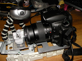
My device looks like this


It also looks like this.

The bit with the "1" next to it is my previously built power supply that delivers 5 volts to my project.

The bit with a "2" next to it is the previously made PICAXE Proto Board that connects some input/output pins to my breadboard.

The "3" is the transistor bit, that powers the motor when the chip sends a signal to do so.

And the "4" isn't really visible. If you could see the "4", it would be next to the the switch that the user presses to make the subject move a tiny bit.

The point of this exercise is to attempt to make a device that carries an empty box of mints along a steady track, to carry a subject to different focal distances, in order to make a series of photos to create a focus stack, and thus create an image with a greater depth of field than might otherwise be achieved.

This absurdly simple solution, represents my first successful attempt at creating an electronic something without external help from someone, somewhere on the planet.

All the software does is wait for someone to press the button, then move the subject a tiny bit closer to the camera. This changes which bit of the subject is in focus, and enables the user to take a "stack" of pics, each one having a different plane in sharp focus. The user can then knit them all together using some free software, creating a photo with an otherwise impossible depth of depth of field.

The 11 lines of code that makes it work look like this (the very small amount of black text is the actual software, the green text is just my description of it)

--------------------------------------------------


; Macro Mover ver 2013 06 10 0200
        ;moves a small platform holding a photographic macro subject a tiny amount closer to the camera         '            each time a button is pressed, helping to create a "focus stack"
;120thingsIn20Years.blogspot.com
;no rights reserved
;use at your own risk

;For picaxe 08M2

#No_Data 'saves a few seconds when uploading the code to the chip, because it doesn't have to check for data

main:' begin the main program loop

if pinC.1 = 1 then gosub Move    'if someone is pressing the button, jump to the bit of code called "Move"

goto main ' if it gets this far, go back to the start and check for a button press again

Move: 'the bit of code that moves the platform with the subject on it

do until pinc.1 = 0 :loop ' hang here until the button is released

high 2 'turn on the motorconnected to pin 2
pause 2 ' wait for 2 milliseconds
low 2 ' turn off the motor connected to pin 2
pause 100 ' pause for 100 milliseconds

      return 'go back to the gosub that called the "Move" code

-------------------------------------------------


I started with an old CD ROM drive that I ripped all the interesting bits out of.

I think this is the original motor because it fits perfectly. This is the motor that made the laser head move from the centre to the rim. Now it's the motor that moves the photographic subject towards the lens, changing which bit is in focus.

The blu-tac is there as a weight to keep the linear cog in contact with the gear that the motor connects to.


So the motor makes the black bit move from this extreme...

(see the black bit)


to this extreme, but in tiny increments each time the button is pressed.

Each button press causes a a quarter of a millimetre migration.

.25 mm = 0.0098 inches

A tiny amount each button press.

The camera sits on the large grey platform to the right.


The software controls how much the motor moves at any given moment. This way we control how much we increment the slice of our subject that is in crisp focus.

The camera is securely set in place because there is a tight fit due to my bending some tags in order to hug the camera. There is also two lumps of blu-tac securing the camera to the base.

This arrangement feels totally secure, and I haven't had any problems with the camera moving.


Last, but far from least, I added a subject platform  and a light source. The subject sits on a platform made form an empty tic-tac (small mint confectionery) box,

The light source is the thing on three zebra legs.

It's best to move the light source with the subject as it moves toward, or away from the camera, to avoid photos with different exposures, so a light that moves with the subject is best.


Once you have a "stack" of photos with different bits in focus, you can knit them all together with a program like "MacroFusion" (free, open source program I run on my linux computer)

To use this Macro-bot device, you press down once or more times, on a button to move the subject a tiny bit closer to the camera. After each button press (or two or three) you take a photo. Each time you press the button, the subject moves a fraction of a millimetre. I found pressing the button once was suitable for macro shots where the lens was at full zoom, and pressing three times when the lens was at minimum zoom.

Some experimentation is required, but as soon as I made this, I immediately solved all the problems I was having with poor alignment of my photos in a focus stack.

Successful results to follow...


120 Things in 20 years - Sometimes, all you have to do to make a robot, is to replace all the bits from the robot you salvaged last week.


Heliostat - What's a heliostat?


I want to start building a heliostat, with the eventual goal of making a solar tracker, but for now, I really want to just build something that will send light through my window.

Why? You may well ask.

And "What's a heliostat?" you may add.

A heliostat is the kind of thing someone with a water drop lensed microscope might have used to get some light on the subject*. Early models involved humans, who were forced to point shiny things in such a way as to reflect the light to shiny men's laboratories. Later versions incorporate wind up mechanisms. For a single day device, all that's required is that it turns 15 degrees every hour, as long as you are willing to manually adjust the elevation for the particular day you are using the device,
a heliostat will track the sun so that a mirror will always reflect to the place I want the light.

The solar tracker is like a heliostat, except that the place it's pointing at is always moving. (that point being directly at the sun wherever it is. But the solar tracker is for another day. Actually all of this is for a great many days.

For now, I'll be working on a small digital device that controls the direction a small mirror is pointing, to make it always reflect light to a fixed point. Basically a way to bring some natural light through a window that doesn't see a lot of light.

There seems to be a few different ways to create some linear movement. Linear movement being required to lift a side of the mirror to adjust the direction of the reflection in the up and down aspect.. I figure if I can raise or lower one side, and make the entire device pivot around a mast, I should have all the degrees of movement required.

According to the invention engine, one way to create the required angle might be to glue a hinge to a mirror, and mount that to a mast to support it. Tie a string to one side of the mirror, then wrap it around a tiny winch mounted half way up the mast, then tie the other end to the other side of the mirror. That would give me up and down, and then all I need is a way to rotate the entire device, perhaps using a geared motor, and a pulley.

I haven't really tackled this bit of the design, but the control of the motors could be done via a PICAXE chip similar to that used in my demand feeder. and some light dependant resistors (LDRs).

If two LDRs were arranged so that when the device was pointing correctly, they were both in full light, but when one became shaded, the motor could be turned in the correct direction to make the adjustment.

A similar arrangement could be made for both the up and down, and rotational movements.

I'm off to an electronics store to buy some stuff.


*may not reflect reality.


120 Things in 20 years is busy finding bits of heliostat. 


Electronics - Low aquaponics water level handling

Previously I mentioned using an alarm rather than employing some way to turn the pump off when the water level became critical, mainly due to wanting to avoid mains power, and all the dying that comes with amateur electronics and it's use.

Wading room only
But I think I may have a better approach to help prevent low water problems associated with leaks or mismanagement within my aquaponics system.


And it's this.

Because I run my pump through a 200 amp hour 12 volt deep cycle battery via an inverter, it occures to me I can just play with the 12 volt supply to the inverter, and avoid playing with my 240volt ac mains power and still turn off the pump if the water gets too low.

Pictured here in sophisticated blue pen (I usually use crayon) is a circuit diagram which will probably shed some darkness on my plan.

Basically, if I control the 12 volt power supply to the inverter, I can control the pump at the 12 volt level rather than at the 240 volt level, and nobody has to die.

Which is nice.

All I need is a PICAXE 08M chip (owned), a 5 volt voltage regulator to supply 5 volts to the chip from the 12 volt battery (owned - thanks pete), and a float switch. (not owned, but $5 (thanks Nom))

This should actually work.


120 things in 20 years of slapping my head because this solution to Electronics - Low aquaponics water level handling should have been obvious from the start.

Electronics - Final board layout

At last it's decided.

I've settled on a hybrid between the two previous designs for my demand fish feeder circuit board layout.

Now we have a small extra board set at 90 degrees for the two momentary (press them on then they go off when you let them go) switches, and the power switch will be on the battery pack.

The board also extends below the main board to allow room for some labels.


There will be three trim pots for in-field adjustment, and this will create settings for the maximum number of feeds per day, the size of those feeds, and the last will be to calibrate when dawn is detected.

I'm not really sure how I'll implement the dawn detection, but it will probably rely on some kind of requirement for an increase in light levels over an hour or something.

Due to the fact that I'm running out of pins to use on the PICAXE 14M2 chip, I only have room for two LED's (lights) to flash out the values for the 3 trim pot settings. This will be dealt with by by having the mode button switch between each 3 trim pots, and the normal operating mode.

The two internal lights will indicate the values by flashing.


  • When the "Feeds" trim pot is being adjusted, the green LED behind it will report it's value.
  • When the "Size" trim pot is being adjusted, the red LED behind it will report it's value.
  • When the Dawn trim pot is being adjusted, both the red and green LED's will flash out it's value.
In experimentation, this has proven to be quite intuitive, and easy to read. 

The dawn setting will probably never have to be adjusted once it is calibrated to local conditions to take account of street lighting etc, so was the obvious choice for not having it's own light.

The other two settings might be changed one a month or so, and as a result were deemed to be more important.

The placement of the buttons on the new circuit board, also allows for my absurdly clever water proof switch idea, allowing the "Feed Now" button to be pressed from the outside.

Which is nice.

The "Feed now" button will light the lever indicator light, telling the fish if they hit the lever some feed will be delivered. This function is in anticipation of the user (me) being overly excited about their new fish feeder, and wanting to see, or show others, the fish triggering the lever to receive feed. It will override the forced wait between feeds, but the feed will still be counted and deducted from their total allowed feed for the day.


120 Things in 20 years, not just Electronics - Final board layout, but also absurdly clever waterproof switch ideas!

Electronics - PICAXE Fish feeder

I'm slowly learning this electronics caper.

I think it's week five now, and I've learnt quite a bit.

I can program a chip just well enough, and almost know enough electronics to make my new improved fish feeder.

It looks like this so far.


What we are seeing here is an incredibly lifelike cardboard fish, acting the part of the hungry test subject.

Currently my prototype allows the user to set how much feed will be delivered by adjusting the length of the pulse to the motor (simulated with the green light).

The user can also adjust the length of time between feeds.

A flashing light (not shown on the video) flashes out long flashes for 10's and short flashes for 1's to indicate the number of feeds so far today. ie 23 would be     long long   short short short (actually very easy to read)

A red light comes on indicating the fish can feed. This will be placed near the lever so as to condition them to the feeding routine. If they attempt to feed when the light is off, they wont get any food.

Eventually there will be a lever in the water that the fish hit when they want feed (tested and working fine - it takes them around 4 or 5 days to work it out)

A light will come on when they can feed, and will be off when they are being too greedy.

There will be a method of adjusting the times between feed, the total number of feeds, and the amount delivered each feed. (probably with a screwdriver so you cant do it by accident)

There will be a switch that reverses the motor, and delivers one days worth of feed via the back of the feeder so you can put a bucket under it and test any adjustments you have made. This test feed can then just be returned to the hopper.

It will have a hopper.

The feed will be delivered via a small geared down motor turning at around 36 rpm, and a screw of some kind.

It's an open source project, (software, hardware, and actual device) and will all be offered freely to make as you see fit. If I can work it, I'll even make a solder-less version that you can put together with a screw driver.

I'll make sure everything I make it out of is easy to find pretty much anywhere.

If all goes well.

not just Electronics - PICAXE Fish feeder - 120 things in 20 years

Electronics - PICAXE 08M Proto board additions

I'm not really sure the level of detail I should go to with this electronics thing.

For instance, the PICAXE system uses a form of a programming language called BASIC, and I think I should at least discuss it a little, but I don't want to bang on about it too much.

What I think I'll do is promise to only put up two posts with computer programming examples.

I think I'll describe the reuse of bits of programs and why its a really efficient thing to do, and I think I'll also describe "If Then"" statements, because conditional branching of program flow is really the way computers do what they do. And maybe variables.

But that's it. Three posts.

And they wont all be in a row.

I'll explain those things later.

But in the mean time I've been learning an amazing amount of stuff and reading everything I can lay my hands on. In fact I've been reading so much that I've forgotten to write about it.

I've also been working on my mini computer.

I removed some bits of my little kit and added a few things to make it a bit more useful to me.

It now looks like this...

I realise you don't know what it looked like before, so you will just have to trust me that this is much better now.

Actually, the previous post has an image of the back of it, but that also fails to incite the excitement in the viewer that I feel, having put the thing together.

Instead of making a torch, I can now make a digital, computerised torch. It works the same, but is much more high tech, and costs a bit more.


The main thing I did was to put a row of contacts on the bottom so I could plug it into a breadboard and play around a bit without the need to solder things.

The breadboard is the white thing, and allows you to poke bits of wire in where clips hold them in place. You can also add electronic components the same way.

This way you can build a fully functional project without committing to soldering it before you have tested it, so you can have everything working the way you want it.

It's amazing to think that in a few months I'll have a new skill. It will be one that I'll spend the rest of my life learning, but I'll be able to do useful stuff with my new electronics skills soon.

I cant wait.

Doing 120 Things in 20 years has turned out to be a very worthwhile thing to do. It takes almost all my time, but I get to learn so much amazing stuff.

It turns out if you stop watching TV, you free up a stack of hours in your life.

Electronics - Picaxe

I bought a PICAXE kit.

It's small.

It has a few bits in it.

That's pretty much all I know so far.

I didn't know I had to put it together so I haven't yet. I have no soldering skills. Who knew melting metal to make metal stick to metal could be difficult. Currently I can make a blob of solder that kind of sticks to the wire bit, but wants nothing to do with the bit that I want the wire bit to stick to.

That's not really soldering.

That's just making wire thicker.

I can make wire thicker. I guess that could come in handy. It's a skill of sorts.

But my kit looks like this.

"A" is the actual PICAXE chip. From what I read it  has around the same processing speed as my first computer. Not bad for $2. It's stuck into some black foam for it's own protection.

"B" is a tiny bit of plastic with some copper in it that is used as a switch to select a connection  between two of the three pins on "H". Both those bits look like they are connected to other bits but that's just my poor photography.

"C" is the circuit board. That's the kind of thing I want to solder the other things to. All the components get attached to the right hand side, and most of the left hand side is blank to allow some space for you to add stuff like switches to control what your chip is doing, or some lights to tell you it is in fact doing something. This is the most simple version of   this system, and I hope to be able to make a few lights flash, and perhaps switch on a fan if the temperature gets too high in my grow house.

"D" is a regular stereo headphone jack. The kit comes with a cord that plugs into your computer, and that headphone jack. This is how you communicate to the PICAXE chip and tell it what you want it to do for you. Everything that's required to understand what your computer is telling it to do, is contained on the PICAXE chip already. Your instructions to it come from some free software that allows you to program your PICAXE chip. The software also came with the kit.

"E" is a yellow thing with some cardboard stuck to the two pins it has sticking out from the bottom of it.

"F" and "F" are resistors. I presume they resist.

"G" is the holder that the chip "A" clips into. Chips are quite delicate, so you solder the clip in place, and then plug in the chip. That way you avoid overheating the chip with the soldering process.

It's difficult to get an idea of scale in the first photo, so I included a rubber chicken of unknown size to offer a sense of scale, and assist your attempts further.

I hope that helps.


Actually, the board "C" is around the length of an AA battery (5 or 6 cm).

So there you have it. It still doesn't mow my lawn or make me drinks yet, so I guess I'll have to start repairing it.

As soon as I bake some cakes and go to a two year old's birthday party, I'll get right on it.

I need a rest after all the study I've been doing. A nice peaceful two year old's birthday party should be just the ticket. Just a crowd of kids quietly celebrating a birthday, and lounging around chatting, eating sugar, and just generally being quiet and calm.

Should be perfect.

Did I mention I have an earache.

Electronics - PICAXE vrs Arduino

I've been madly reading everything I can get my hands on to compare these two mini computer systems. 


Scanning electron crayon image of actual electricity
Arduino is an open source platform where a stack of different people build lots of different bits that all plug into each other and do all kinds of amazing things. You program them in a computer language called "C".


PICAXE is a company that does lots of work with the education system in the United Kingdom, which is run by a queen, and is programmed in a computer language called "BASIC". [the chip not the queen]


She's also the queen of Australia. 


Which is odd. 


I'm not normally a fan of non-democratic state organization, and the queen is far from democratic. But I'll buy stuff from her country in spite of all that. As far as I know the people of PICAXE don't actually know the queen or have anything to do with her. And she does seem like a nice enough old lady. 


So I'm going with PICAXE.


Another reason I'm going with PICAXE is they were the first people I found, and I've already read a lot of their manuals and things. They are also cheap (to buy bits from, not as individuals (well maybe, I have no idea)), have a good reputation for prompt delivery, and the big seller from my point of view, they make a board called a shield base that is open source compatible. I think that means I can use the best of both worlds. 


A shield is a pre-built device that talks to, and plugs into, the main device. So if you want to control something like a fan in a glasshouse, you can use a thermometer connected to your main device (that might be called a shield base), then plug the motor control shield into it. This way you could perhaps turn the fan on in the glass house if the temperature got over 30c or something. The bit that controls the higher voltages of the fan, can be all dealt with without me having to reinvent the wheel. 


I'll be reinventing the wheel though, as I want to learn electronics. I'll probably end up using a bit of everything. 


A lot of people have made a lot of different things that already do interesting stuff, so you can plug that interesting functionality straight into your project.


But doing something like using a shield is a long way off. I have to learn to solder, and make pickles first. I suspect my first real world project will be to revisit my automatic fish feeder, that the fish operated by pressing a lever.


So, in short, PICAXE seems to be able to do whatever it is that I think I might want to do, and wont cost very much. Cost is important, because my entire 120 Things in 20 years have to be self financing. I borrowed the set up cost of the aquaponics system from myself, and roughly work out savings based on the supply of vegetables etc. coupled with some advertising revenue and my aquaponics pump and other goodies I won from the photographic competition, After buying my glasshouse and some extra plumbing, I have just enough left to refill the sugar bowl after making my first marmalade, and start on my new electronics "thing".


Electronics - PICAXE

PICAXE is a brand name that sells electronic bits. As far as I can tell they work a lot with the education system within the UK.

That and the fact that they seem to make interesting looking stuff is all I really know about them so far, but I think they might be the people to help me along, far as getting started on this understanding electronics "thing".

They make programmable chips, and stuff like temperature sensors, robot motors, remote control stuff, battery holders, and what looks to the novice to be just about everything someone like me could want.

As far as I can see, you get hold of an experimenter board, designing your project temporarily on it, then program your chip by plugging the board into your computer. Then once it's all tested and ready to go, you solder it all in place on a circuit board to make a permanent version.  Next, you install it into your lawnmower, ask the newly installed robot arm on your fridge to pour you a drink, and watch your lawn mow itself.

That's my plan anyway.

Actually my plan is to make something that will open the glasshouse door if it gets too hot inside.

I've tried to understand electronics before, but I think I need a practical way to study rather than by reading books. I borrowed a few books from my library about a year ago when I wanted to blackout proof my aquaponics pump, but stuff like this just doesn't stick in my head unless I do something with it in the real world. My current understanding is a general idea about how stuff might work. I could make a torch, but I couldn't make it turn itself on in the dark.

Generally speaking, I've avoided mentioning brand names on this blog, but this time I think I'm going to have to. Each of the different companies make their own versions of these kinds of things, and as far as I can tell, their components are not necessarily compatible with each other.

Around 25% of the readers of this blog find their way here by search engines looking for a particular bit of information, so by mentioning the brand name, it makes it possible for the reader to know if I'm talking about the same stuff that's sitting on their desk.

I'm not getting advertising or any free stuff from them, although I would gladly accept it (if ever anything like that happens I'll let you know). I found their product through google adverts like the ones on my page, so there is a chance their ads will appear on this page because adverts are topic dependant. So if someone was to click on one of their ads, I would gain a small amount of money from them, but I wouldn't know it was from them and not a different advertiser.

What I'm trying to say is that I am not endorsing the product and I'm not knowingly being paid by them or anything. But I will let you know what I think of their product as I become familiar with it..

Other than opting out of adult content ads, I have no control over which ads Google displays on these pages.

I know nothing about this brand and have no opinion on the PICAXE quality or business practices.

No doubt that will change soon, because I'm about to buy some of their stuff!


Popular Posts